|
1. SPECIFICATIONS
DIMENSIONS
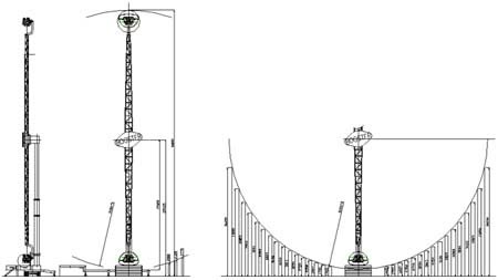
Height : 40.0 metres / 131
Width : 13.6 metres / 61
Depth : 07.5 metres / 25
VEHICLE : 2 vehicles - 4 seats each - 8 passengers max.
LOADING : 1 vehicle, 4 passengers at a time
ESTIMATED CAPACITY : 120 passengers/hour
SUGGESTED RIDE DURATION : max. 1 minute
POWER (installed)
Motors (DC) : 95 KW
Services : 05 KW
Lights : 20 KW (standard package)
Required for connection city line : 180 KW - 310 AMPS
Generator suggested : 250 KVA
Main application : three phase + neutral + ground
Voltage : 380 Volt 5% (other versions on request)
Frequency : 50 Hz (other versions on request)
SPEED : 12 RPM - 82 Kmh - 52 Mph
ACCELERATION : 3.6 G max.
WEIGHT : 38 Tons
TRANSPORT : 1 Trailer 13,6 mt - 45
INSTALLATION : 3 people, 6 hours
|
2. CALCULATIONS AND ENGINEERING
The stress analysis and designs of FC Fabbri Park BOOSTER ride are in conformity with DIN standards, and the electrical system is in conformity with EN-60204-1 standard.
Upon request, the ride can be supplied with TÜV approval.
|
3. DESCRIPTION
The BOOSTER ride is made up of one telescopic column hinged to the trailer, which is lifted to the vertical position and raised to the max. extension hydraulically. Two rotating arms are installed on the upper part of the column by means of a swinging bearing. The arms are locked in proper position by steel pins electrically operated. At the extremity of each arm there is a four passenger back-to-back vehicle, with dangling legs system. A parking brake allows safe passengers access to and from the vehicle. Every seat is provided with a safety shoulder bar with double restraint system, the shoulder bar is air operated.
The arms rotate by means of two D.C. motors while the vehicles are free to rotate according to the speed and centrifugal force, they can perform a 360° rotation (loop). The vehicle speed is variable and can reach a maximum force of 3.6 G. The height and high speed are extraordinarily spectacular.
|
1- Movements
- 360° rotation of the arms (clockwise and counter-clockwise) Speed: from 0 to 12 rpm
- 360° rotation of the vehicle (clockwise and counter-clockwise) free
2- Ride Control
The ride is provided with a fail-safe system control. All the ride operations, the control of both direction and rotation speed of the arms are performed manually by the operator by means of a potentiometer. Also the engagement/disengagement of the pneumatic brakes is up to the operator. Of course all these operations are controlled by the DC controller, which guarantees that the maximum values set (volts, amperes, ramp, speed) are not exceeded. These values are set according to the data obtained from the stress analysis.
Moreover, the insertion of the electrical parking brake, the opening of the safety lap bars and of the secondary safety small cylinders, and all the lights are controlled from the control panel.
The main electrical panel must be located in a control room provided by the Customer, where the inside temperature cannot be lower than 5°C nor exceed 30°C and where humidity must range between 35% and 70%.
3- Safety devices
During the ride operation the safety of the passengers is guaranteed by the following:
- Overhead lap bar for each seat. This is a steel bar made soft by a layer of foamed polyurethane and which can be fixed in different positions in order to provide a perfect adherence to the passengers body.
- Each bar is kept closed by a double locking rack mechanism positioned at the back of the seat which guarantees the highest safety: its closure is automatic, while its opening is controlled by the operator by means of a pneumatic system. Moreover, the mechanism is constantly controlled by means of a micro-switch.
- Seat made of moulded foamed polyurethane with special protection in order to prevent the passengers from slipping under the bar. The seat is completed by a polyurethane headrest.
- A series of electrical safety devices, together with pressures switches installed in the line, interact with the D.C. controllers thus preventing the ride operation in case one of the safety lap bars is not perfectly locked and during the loading/unloading of passengers.
- In case of emergency or of blackout, the passengers are never exposed to danger since the safety lap bars always stay perfectly closed and will have to be opened manually once the ride has stopped for inertia.
4- Drive System
The rotation of the arms is obtained by means of a swinging bearing, driven by two pinions, connected to two epicyclic gear boxes powered by DC motors while the vehicle, though installed on two swinging bearings as well, rotates freely. The power supplied to the motors is entrusted to specific DC controllers which control power quantity and supply times besides checking the proper operation of all the safety devices.
An electric brake installed in one of the two motors and two pneumatic brakes installed in the vehicle keep the ride in its correct position during the passenger loading/unloading phases.
5- Mechanical Parts
The swinging bearings of the arms and vehicle are manufactured by Rothe Erde.
The gear boxes of the arms and vehicle are manufactured by Brevini.
The pneumatic brakes of the vehicle are manufactured by Twiflex.
Electric and Pneumatic Equipment
The DC controller 350 Amp. for the arm rotation is manufactured by ABB.
The DC motor RTL PVR 160S 72 KW for the arm rotation is produced by Comer.
The micro-switches are produced by Crouzet.
The compressor 50 lt., 2 HP, 1.5 KW is produced by Fini.
The safety lap bar pneumatic cylinders are manufactured by Camozzi.
Illumination (optional)
The standard package is made up of:
8 lines of rope-lights (plastic) on the arms;
large luminous sing installed on the centre whit cabochone;
lights on the vehicles.
|
|